
One of the problems of creating a fire-control system is transmitting data between its various elements. Directors, mounted high up, need to be able to talk to the plotting rooms, and the plotting room needs to be able to issue orders to the turrets. Many different methods have been devised to solve this problem over the years, and they deserve some attention of their own.
The fire-control transmission paths in a late-war US system
At first, all data had to go between the various bits of fire-control apparatus by voice. While shouting was traditional, it was also easily covered by the din of battle. Instead, voice pipes were used. A voice pipe is a simple tube with a cone on each end, the cones shaped to match the impedance of the room so that sound is transmitted well through the pipe. A device of this type can be found on playgrounds worldwide,1 and while it's primitive, it's light, simple, and not reliant on electrical power. The only potential drawback is that it provides a path for fire and flood to spread, but this is easily handled with a plug. Over longer distances, telephones were used.
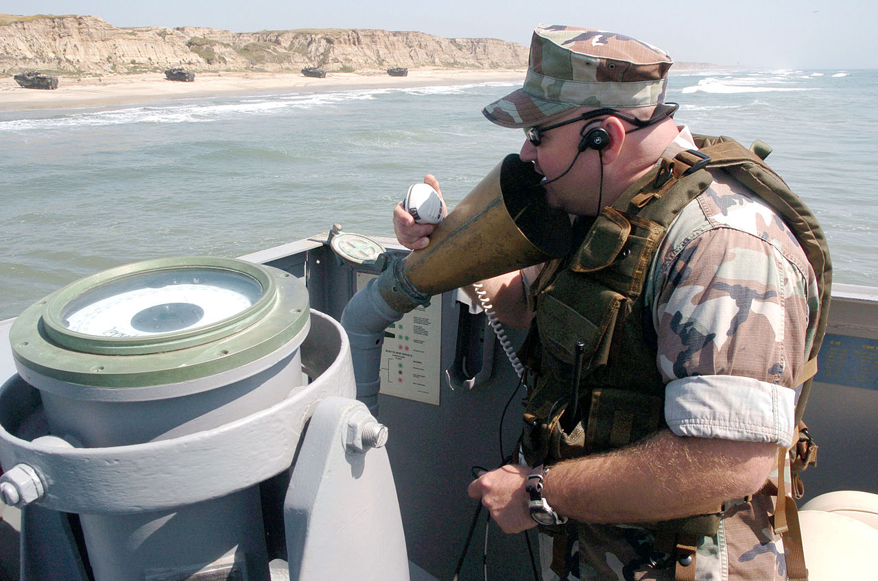
A voice tube in service on a modern landing craft
The biggest drawback of any scheme involving transmitting fire-control data verbally is that it is slow and unreliable. Reading data off, say, a rangefinder and passing it to someone else takes time, and introduces the potential for the recipient to mishear it amid the chaos of battle. Unfortunately, the technology of the day made non-verbal data transmission difficult, and a great deal of ingenuity was deployed to solve the problem. The first effort, from Barr & Stroud, the rangefinder manufacturers, used a dial driven by a clockwork mechanism so long as an electric current was on. Moving the transmitter to the desired location turned the current on for the relevant amount of time, then switched it off again. Trials showed that this device didn't work particularly well. The biggest issue was that the dial was hard to read precisely, and the British decided that a mechanical counter, which could display digits directly, was a better option. Because this was a discrete (digital) counter, it naturally suggested the use of a pulsed transmission which moved the receiver a fixed step each time it was sent, which became known as the "step-by-step" system.
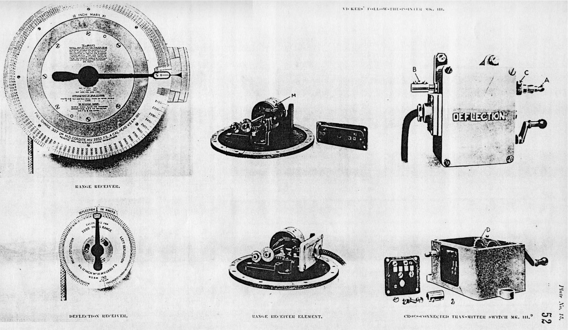
Vickers step-by-step recievers
In service, the mechanical counters proved disappointing. Electrical systems of the day also couldn't easily be used to directly drive more than a counter or pointer, so a human was needed to bridge the gap between the incoming data and the value that needed to be changed based on it, like a gunsight. Trials showed that the best way to do this was to create a dial with two pointers, one showing the desired position of the system from the transmitter, the other displaying the current state. The operator merely had to match them, and the system was thus known as "follow-the-pointer".
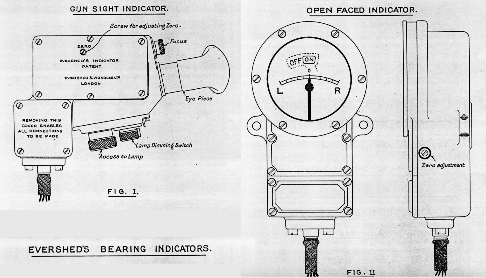
Evershed bearing indicators
Another system developed to support this was the Evershed transmitter, which used a version of the wheatstone bridge. In this, a special electrical circuit was created where any difference in direction between the transmitter and receiver would cause current to flow, and a galvanometer could indicate to the recipient how far off they were. In practice, it wasn't precise enough to replace the step-by-step transmitters, but it was incredibly useful for making sure that all the elements of the fire-control system were actually looking at the same target.2
The step-by-step system was relatively simple to implement, but had serious drawbacks. It essentially passed movement instead of position, so it relied on the transmitter and receiver staying in sync. If a pulse was missed, because of an interruption in power or simply because the transmitter was turned too fast and it arrived before the previous step had been taken, they would get out of alignment and ultimately have to be manually re-synchronized. Later systems had several positions and could tolerate some degree of misalignment, but still suffered from another drawback. Any restructuring of the fire-control network, for instance from the primary to the secondary director, required the system to be realigned.
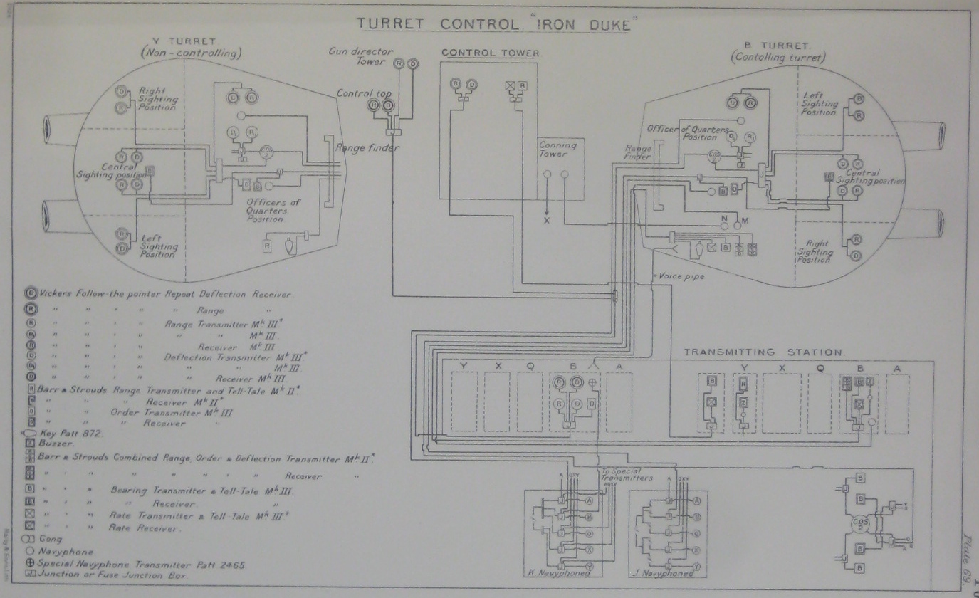
The main-battery fire control system for Iron Duke
To solve these problems, the British devised another system. When the transmitter was turned, it made an electrical contact that drove a motor attached to the receiver. This also turned a step-by-step transmitter that passed how much the receiver had turned to back to the transmitter. The transmitter stored how much input had been made using a differential, with the other side driven by the step-by-step receiver, which cancelled out the input. The motor was set to run slower than the transmitter's maximum speed, and if the power went out, the differential would store any inputs. Even better, the system could drive more than one receiver, which made it much easier to switch between inputs.
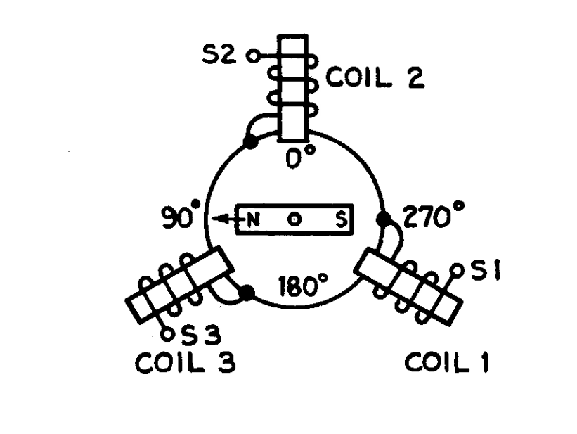
A synchro
But this was ultimately a second-rate solution, driven by the British use of DC current in their ships. The Americans and Germans used AC electrical systems, and were able to make use of a vastly superior device, the synchro. This is a self-aligning device which transmits the position of the rotor in the transmitter to the receiver via electrical witchcraft.3 Synchros are continuous, which allows more precise transmission of positions, and self-alignment makes switching between input devices or recovery from power outages relatively painless. Even the British eventually came around, and synchros dominated the last generation of battleship fire control transmission.
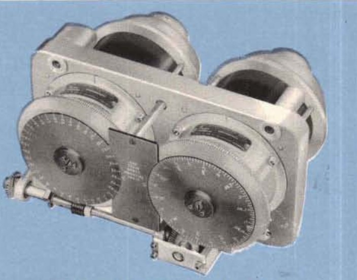
A two-speed synchro
However, the available precision was still limited, and the increasing accuracy of naval gunnery meant that a synchro which transmitted precise values would have to rotate many times over the range of values needed. This brought back the old alignment problem. A bearing synchro which had to cover 360° but turned once for every 10° of bearing couldn't easily distinguish between 5°, 15° and 255°. The solution was "two-speed transmission", fitting two synchros, one which turned once per 360° while the other turned every 10°. They would simply be geared together on the transmitter end, while the receiver would have two dials, which together gave the full range of values.
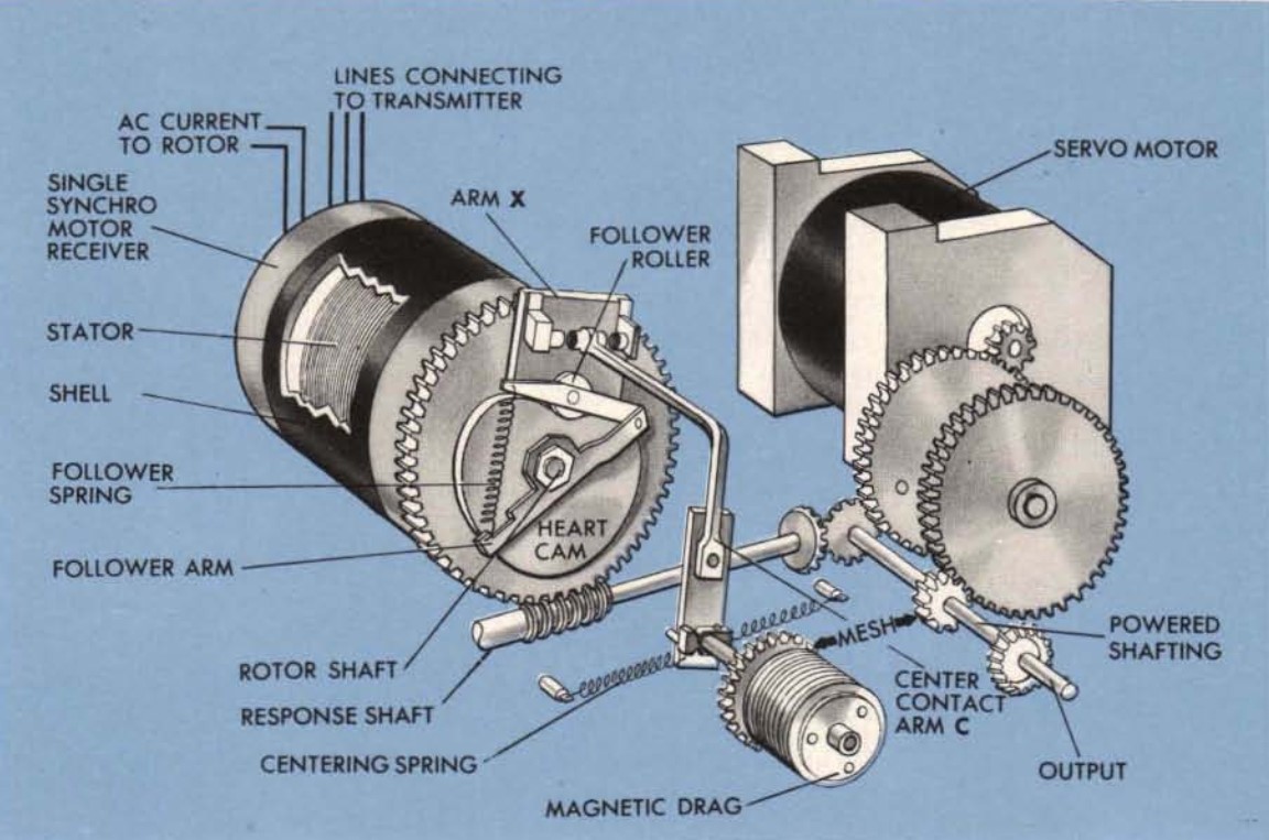
A synchro-driven servo
Synchros, unfortunately, were no better at exerting torque than were step-by-step transmitters, and devices known as follow-ups had to be used to amplify their signal, even if it was only going to be fed into a fire-control computer. A follow-the-pointer system was a simple version of this,4 with the operator serving as the follow-up. But by the 1930s, servo mechanisms had been developed which allowed the synchro to control a much stronger motor. When the rotor of the synchro began to rotate, it would close a set of electrical contacts which turned on the servo motor in the relevant direction. The shaft coming out of the motor was geared back to rotate the stator of the synchro5 so that the contact was broken when the servo had turned the output to the correct position. This process, while simple enough in theory, required specialized mechanisms to deal with cases like a power outage to the motor, which could keep the rotor turning and damage the contacts. A heart-shaped cam was used to prevent this from happening, with the cam allowing the rotor to move the contacts up to a certain point, then cutting in to interrupt the process and prevent damage. Two-speed transmission required more complicated mechanisms to pass control from the fine synchro to the coarse synchro and back again as necessary.6
Electro-hydraulic RPC for a 5"/38 mount
The ultimate goal was to remove humans, and thus human error, from the task of positioning the guns. Remote Power Control (RPC), where values went directly from the computer through servos to aim the guns, was faster and more accurate than follow-the-pointer systems, although it was still not universal by the time WWII broke out. The USN had full RPC, while the Germans used it only in elevation, leaving train in manual hands. The RN, still limited by DC electrical systems, only fitted it to some ships late in the war. RPC required even more power than the servo follow-up mechanism did, so more complicated means of amplification and control were used. The USN used electro-hydraulic RPC systems for big guns, and amplidynes for smaller ones.
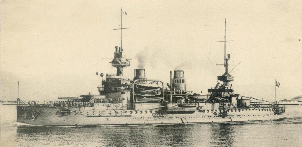
French Battleship Saint Louis, one of the ships fitted with the Germain system
There is one other system that deserves to be highlighted. In the first decade of the 20th century, the French used the unique Germain hydraulic system. This was a rather simple and ingenious system, with a single hydraulic line connecting the turrets with the fire-control station. Each receiving station had a gauge to read the pressure on the line, calibrated to show gunnery data instead of the actual pressure. It was cheap and reasonably reliable, but had two serious problems. First, there was only a single line, so one dial had to get not only range data, but also train and firing orders, which limited precision. Second, the hydraulic line had to pass through the boiler rooms, which heated the fluid and changed the values received by the aft turret. Eventually, it was replaced by a conventional step-by-step electrical system.7
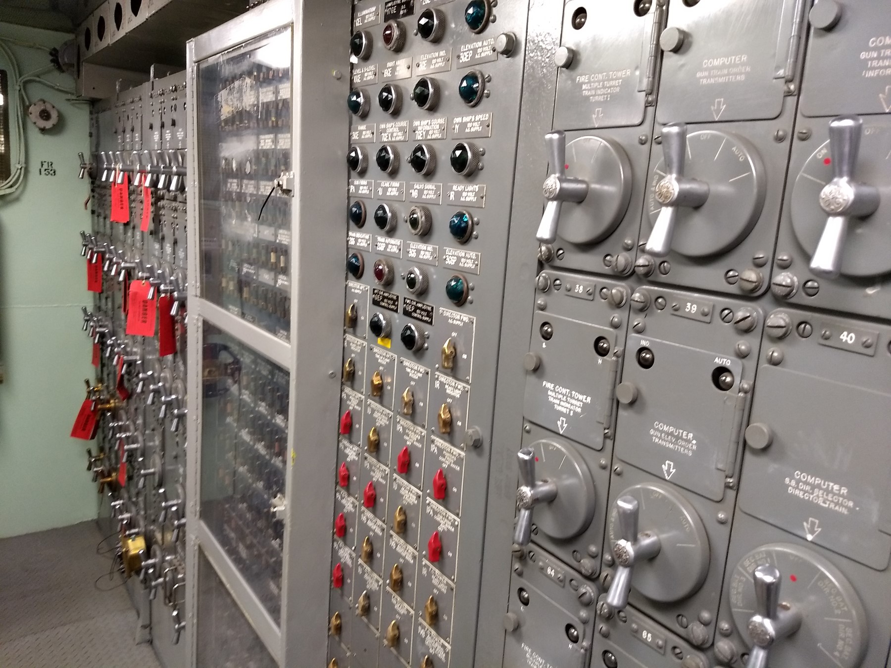
The switchboard in Iowa's aft main battery plotting room
Despite some missteps along the way, the technology available for passing information within a fire-control system grew tremendously in the first 40 years of the 20th century. Without a good way to remove the delay and error of human intervention from the mix, fire control could not have advanced much beyond its state in 1900. But a tremendous amount of ingenuity allowed Iowa to turn data entered by the director crew into guns pointed at the target without a single sailor having to lift a finger.
1 Yes, I did ask SSC about this, just to be sure. ⇑
2 Yes, this was a surprisingly common problem, particularly when rangefinders were separate from the directors. ⇑
3 OK, it's not actually witchcraft, but it's not particularly easy to understand unless you're an electrical engineer. If you want more details on these devices, see the US Navy synchro manual. Synchros are amazing because they also give feedback, and they're still used in some military aircraft control systems. ⇑
4 The British traditionally used the members of the ship's Marine Band (for complicated historical reasons, the RN's music is provided by the Royal Marines) as follow-ups in the plotting spaces. ⇑
5 This is because you can't move the rotor, which always wants to be in the same position relative to the stator, and rotating the stator to hold the rotor in the same position is mechanically much easier than moving the electrical contacts around. ⇑
6 For more details of how this worked, check out Section 3 of OP 1140 (Basic Fire Control Mechanisms. It's a basic manual on these systems, with simple explanations and a wealth of details on the thought behind these systems. ⇑
7 I am aware of one case where mechanical shafts were used for passing data between elements of a system, instead of just within an element. This was the British War Emergency Destroyers, which had shafts from director to transmitting station. This was probably a result of wartime demands on the precision electrical industry, and forced the director to be mounted low to keep the shafts short. ⇑
Comments
Glad to see witchcraft finally getting the recognition it deserves. All too often witchcraft, hoodoo, and magic smoke are overlooked in technical publications, despite their ubiquitousness in the field.
However, the available precision was still limited, and the increasing accuracy of naval gunnery meant that a synchro which transmitted precise values would have to rotate many times over the range of values needed. This brought back the old alignment problem. A bearing synchro which had to cover 360° but turned once for every 10° of bearing couldn’t easily distinguish between 5°, 15° and 255°. The solution was “two-speed transmission”, fitting two synchros, one which turned once per 360° while the other turned every 10°. They would simply be geared together on the transmitter end, while the receiver would have two dials, which together gave the full range of values.
I think I know what you mean with this paragraph, but I'm really not sure. It might help to explain why the syncros are spinning.
Spinning is the only thing synchros do. The problem is that they only position 0-360. They can't do more than that, and they only do that with a finite accuracy. So sometimes you need to use more than one to get both the full range of values and the accuracy you need.
Did they ever try and use mechanical or hydraulic lines instead of electronic? Something like a bicycle shifter cable seems like it would work. If cables, pushrods and bell cranks are good enough for aircraft controls shouldn't they work here?
@Gareth
Bowden cables on a ship would have to go a lot further than on a bike or an aircraft.
Thermal expansion sounds like it would cause inaccuracies. Corrosion could also cause the whole thing to seize up.
Hydraulics were used, as described in the main post. Mechanical linkages were common between elements in the same room, but never used for long-distance transmission AFAIK, for a bunch of reasons. Besides the ones Lambert mentions, all of which are true, you have to consider that the system had to be something you could refit to existing ships. Mechanical controls don't work well for that at all, because you'd have to thread them around the ship's existing infrastructure, and every pulley is a place for things to go wrong. Also, ships are a much less "clean" environment than airplanes. Electrical wiring is less vulnerable to mechanical damage, more resistant to corrosion, doesn't suffer from friction, and takes a lot less maintenance.
Another aspect is that aircraft controls have to transmit a lot more power than ship FC systems do. They have to at least move the tabs that direct the main surfaces, because you can't station someone to act as follow-up out on the wing. If you needed that sort of power, then mechanical linkages would make a lot more sense.
Well this is strange. I've been posting under "Gareth" in the Rule the Waves threads and some other threads. Unless I've had a very specific out of body experience, I didn't post that mechanical/hydraulic lines question.
@Gareth- have I just managed to stumble upon someone who shares my name and lack of creativity with online usernames, or is this a convoluted identity theft scheme?
I can probably rule out out-of-body experiences for you, as it's a different email from the one you use.
Curses, foiled again!
@Bean- Thanks for confirming that. Nice to see the email address isn't leaking strangely at least (and that I'm not sleepwalking to my laptop in the middle of the night)
"allowed Iowa to turn data entered by the director crew into guns pointed at the target without a single sailor having to lift a finger" I fully accept the general point and they were excellent systems but, out of interest ... is it not the case that quite a bit of sailor input was required for effective aiming ? Wasn't the target range/inclination estimated by a human ? .... and revised, when prompted by an actual/prediction mismatch ? Also, did not a few other, maybe more minor tweaks likely need making at the Mk8 to generate an improving solution ? Great site & info BTW :-) JG
Obviously, the data entry in the director was manual, but everything after that could be automatic. But yeah, usually there would be some manual work afterwards, like putting in spots. The big difference from previous systems was that they didn't need manual work.