
Developing the technology required to keep the military of the US and our allies on the cutting edge isn't easy. It requires billions of dollars and tens of thousands of people, all working to push the equipment available forward. A lot of this work isn't particularly glamorous or exciting, but occasionally, it requires some truly incredible facilities.
The David Taylor Model Basin
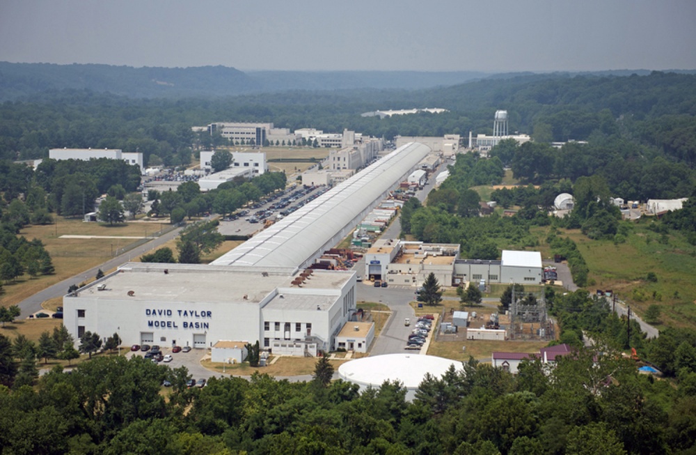
My favorite of these is the David Taylor Model Basin in Carderock, Maryland.1 This is "Where the Fleet Begins", the place where the Navy does the basic research that ultimately feeds into operational warships. Even today, computers are not capable of the accuracy needed when simulating the flow of water around a ship. To make sure that our next vessels will be as fast and as seaworthy as they need to be, physical models must be tested. And the best way to do that is to create a giant tank and tow a model through it. Of course, it's not nearly as easy as it sounds,2 and DTMB is one of the world's premier facilities for such research.
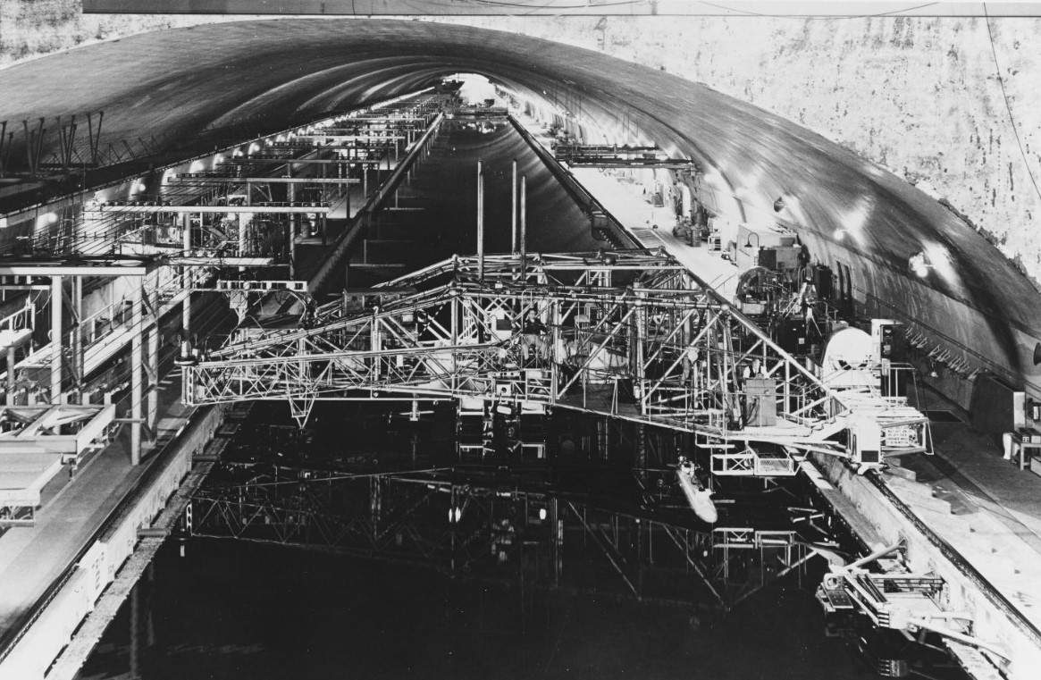
The deepwater basin, with the towing carriage
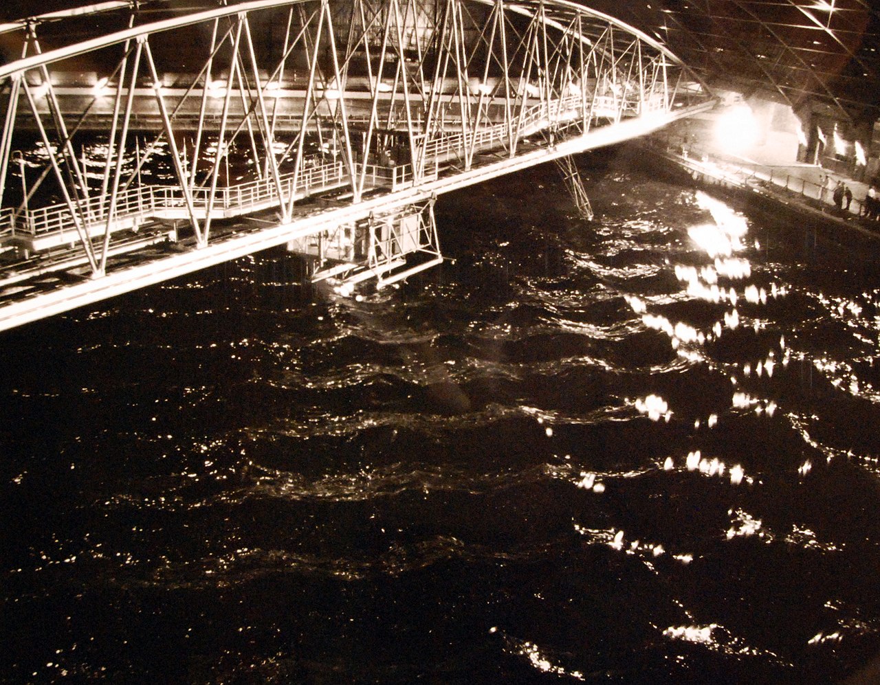
The heart of DTMB is the three towing tanks: the deepwater basin, the shallow-water basin, and the high-speed basin. The deepwater basin is 2,775' long, 51' wide, and 22' deep, and is fitted with a wavemaker capable of simulating heavy seas, which can have a significant impact on ship performance. The towing carriage over the basin can travel at up to 20 kts, dragging a model up to 32' long and weighing 5 tons and precisely measuring the forces it takes to do so. The shallow-water basin3 is at one end of the deepwater basin, and they can be connected if needed for certain tests. It is 303' long, 10' deep, and ends in a 180° J-turn used for testing turning performance. A model will be towed by the carriage up to speed with its rudder fixed in a turn, then released. When the basin was built in the 1940s, tracking was done by fitting the model with lights and dousing all others in the building, then filming the turn. Today, the turning basin is rarely used, as other facilities are better for this type of analysis.
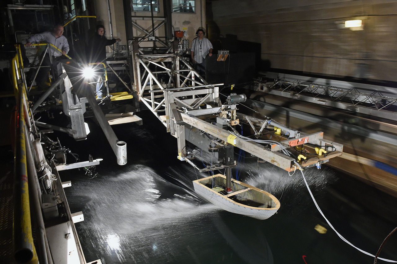
A hull is tested in the high-speed basin
The high-speed basin runs parallel to the two other basins, a full 2,968'. It's only 21' wide, and the depth varies from 10' to 16', but one of the carriages can tow models of high-speed craft, hydrofoils and seaplanes at up to 60 kts. All of the basins are fitted for photographic studies as well as towing force measurements, and were specially leveled to within .005", following the curvature of the Earth. The models used in them are built by DTMB's own model shop, and for decades were hand-crafted to the lines given by naval architects.
The MASK facility
Backing up the towing tanks is the Maneuvering and Seakeeping Basin (MASK). This is a one-of-a-kind facility designed to replicate virtually any sea conditions using 216 independent electromechanical wave generators. Models can be towed through them at any angle to measure the forces involved, or free-running models up to 30' long can be used in the 360' x 240' tank. The same building also has a rotating-arm system designed to measure the performance of ships while turning. The basin is 260' across and 21' deep, with an arm on the stand in the center. Models towed from it can reach speeds up to 50 kts in a single revolution, and give unique information on stability, control and maneuverability.
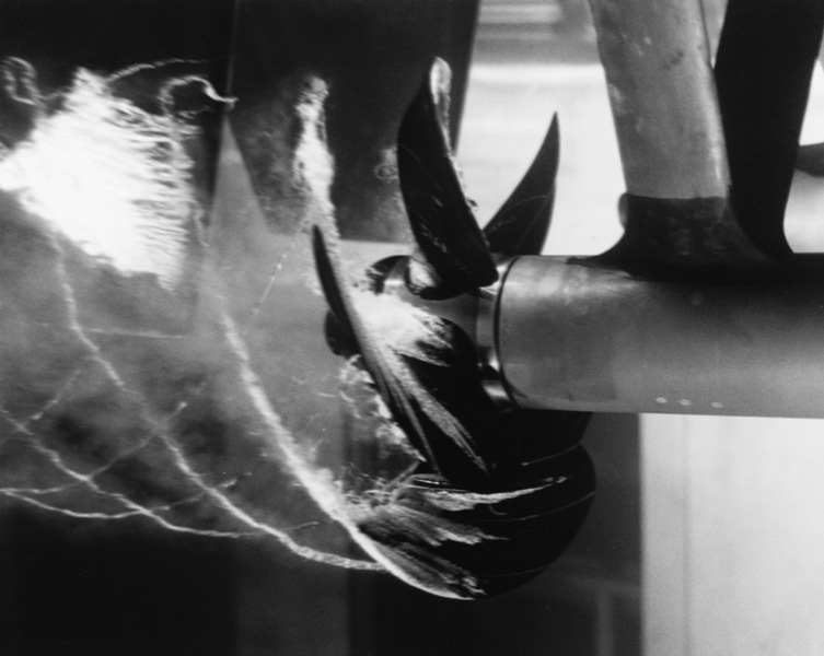
A propeller cavitates in the water tunnel at DTMB
Nor are model basins the only interesting and unique capabilities at DTMB. Despite the old-school methods used to get much of this data, the facility has been on the cutting edge of computer modeling of ship motion and other effects since 1953, when it received its first digital computer, a UNIVAC I. It has facilities for acoustics research, including an anechoic wind tunnel,4 a circulating water channel that allows hydrodynamic analysis on a static model,5 and a number of pressure tanks that are used to validate submarine equipment and even scale models of submarine hulls. Several water tunnels are used to study propeller designs, and labs specialize in ship materials and structures. The largest underwater explosives test pond in the country is at DTMB, and it's fully equipped for underwater photography to help develop structures that can resist underwater explosions.

Foundations are laid for the towing tanks, 1938
For more information on DTMB, check out this article on the towing tanks from a 1943 issue of Popular Science and the book Where The Fleet Begins, a history of the facility through 1998. I was privileged to be able to visit NSWC Carderock in October 2021, and have written up my experience here.
1 David W. Taylor was a naval engineer who, among other things, set up the organization that would eventually become DTMB. I later figured out that the organization as a whole is more accurately referred to as NSWC Carderock, while DTMB is just the towing tank, but will leave this post as-is. ⇑
2 I'll talk more about the specifics of model testing and the history of the discipline later. This post is only about DTMB. ⇑
3 Shallow water can significantly change the hydrodynamics around a ship, so a specialized facility is needed to investigate these interactions. The shallow-water basin is often used for things like tugs and riverine craft, which routinely operate in these environments. ⇑
4 This is a wind tunnel designed to allow the measurement of flow noise over the object being tested. Most wind tunnels are very noisy and would not be at all suitable for this. As to why a wind tunnel, water and air can be correlated under most conditions, and it's probably a lot easier to silence a wind tunnel. ⇑
5 It's much harder to get water to flow smoothly than air, which is why towing tanks are generally used. The static tunnel has the advantage of allowing extra measurement equipment that couldn't follow a towed model. ⇑
Comments
On your last footnote, I've got two related answers for you. First, 51' x 22' x 20 knots multiplies up to 17,000,000 gpm. That's two of these: https://www.popsci.com/scitech/article/2009-08/saving-new-orleans-worlds-largest-water-pump/ . I think that might be a tad bit pricey, and a dramatic engineering challenge to build.
In addition, wall effects and turbulence from the pump, pipe bends, etc are significant. I've run into that as a chemical engineer when looking at pipe hydraulics and flow measurement, but I'm sure it applies to this application as well. If the water is stationary compared to the wall, you can ignore the turbulence and wall effects (well, partially - I bet there's a limit to how close the ship model can get to the wall before ruining the data). Moving water tends to be turbulent The only way to smooth out a water flow is to give it a lot of straight-run distance. The rule of thumb in a chemical plant is 10 pipe diameters - which here is 10 x 51' = 510' just for the flow calming section, before taking any space for the actual ship model or the pumps. Chemical plants generally are willing to tolerate imperfect data because they just need to run, they're not building any theories off their data, so 10 diameters is probably not even enough for this application.
So a moving-water system would cost a lot more to build and operate, give worse data, but maybe save some on land. The only real advantage I can see is that a test wouldn't be limited to a minute (time to go from one end of pool to the other at 20 knots). Still, you can learn a lot in a minute. I'm not surprised they chose to take advantage of a moving reference frame instead!
Interesting. I hadn't thought of the flow volume issue, and it's good to have hard numbers on how much time you need for the flow to smooth out.
There are definitely wall interactions that need to be accounted for if you get close enough, although I think the towing tanks are big enough to minimize those.
Running the numbers for water flowing through an open channel like that gives a Re of around 30 million.
If you look at a Moody chart, you'll see that you'd need impossibly smooth channel walls to avoid any tubulence.
I recently read of an issue with trying to get good results in a huge "tank" of air.
Doing measurements on the power required to ride a bike at a given speed around an indoor cyclodrome.
Having one other bike on the opposite side of the track also going around in the same direction produced a measurable reduction in the power required to cycle at a given speed. A reduction comparable to the effects of the improved aerodynamics etc. that were being tested.
Developers can chase their tails for ages because they haven't removed one hidden source of noise in the system.
This is a ludicrous statement to make, even in 2019.
Might I ask what experience you have with CFD to be calling that ludicrous? Yes, it's valuable, but it's not good enough, cheap enough, to replace the towing tanks.