
The basic principle behind radar is fairly simple. The radar sends out a pulse of radio waves, some of which bounce off of whatever happens to be in their path. These reflections are picked up by the radar and used to build a picture of whatever happens to be out there. But this simplicity masks deep complexity, as various portions of this are implemented in different ways, and even from the earliest days of radar at sea, ships carried multiple sets optimized for different missions.1
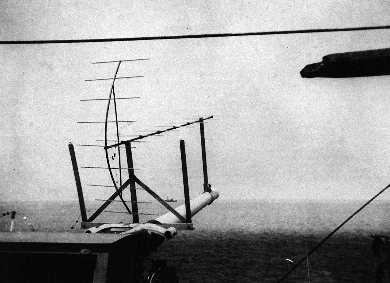
The first USN at-sea radar test aboard the USS Leary, 1937
The first radars, as developed in the late 1930s, were extremely crude. A transmitter would send out a short pulse through an antenna shaped to focus the signal in a particular direction, and then switch over to listening for the echos through the same antenna.2 The returned signal would be displayed using a device known as an A-scope, a special cathode ray tube. Essentially, the A-scope would draw a horizontal line for each pulse, deflected up (or down) depending on the received signal strength at a given range as measured by the round trip speed-of-light delay. An object reflecting the beam would appear as a spike or trough on the line, depending on how the A-scope was set up. This gave the operator precise knowledge of ranges, a vast improvement over previous methods, but only in the direction the antenna was pointing. Checking different bearings required rotating the antenna, often manually, and left the operator with the job of keeping track of what was going on around him. This didn't make it impossible to use radar data to build a picture, as the British did with the Chain Home radar feeding information to the Dowding system, but this took lots of manpower and organization.
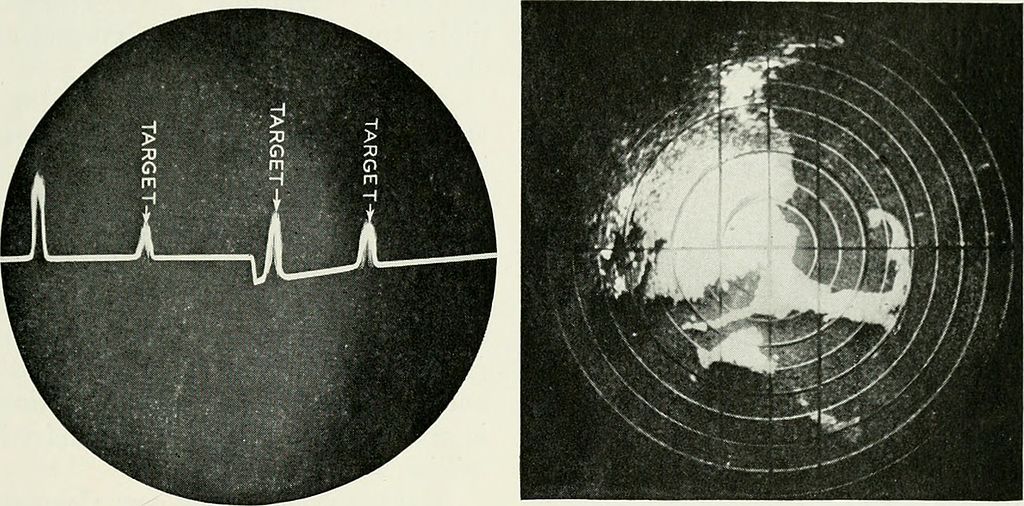
An A-scope (left) and PPI (right)
The solution was to use different kinds of radar displays. The most famous is the Plan-Position Indicator, or PPI, the classic radar display. In this system, the radar is spun automatically, pulsing as it goes. The display shows the radar itself at the center, and draws a "line" along the bearing it is pointed at, much as the A-scope does. Unlike the A-scope, the PPI varies the brightness of the spot in proportion to the returned signal strength, showing each target as a blip with both range and bearing. Usually, the blips fade out after a second or so, but with the radar sweeping back every few seconds, it is far easier for the operator to keep track of the situation. Nor was the PPI the only alternative to the A-scope. Particularly for aircraft and fire control radars, which didn't have to search their surroundings, a common setup was the B-scope, which displayed range on the Y-axis and bearing on the X-axis.
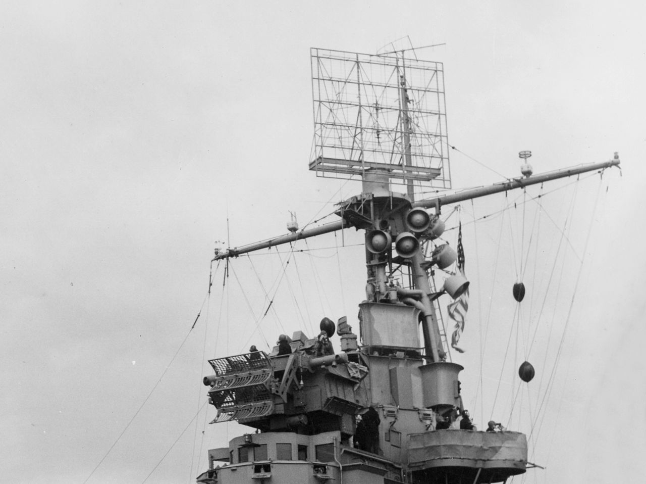
CXAM air-search radar and a Mk 4 fire control radar aboard USS Ranger
So far, all of this is reasonably straightforward, but if it's all this simple, then why have all warships since the early 1940s sprouted so many different types of radar? The answer is that the performance of a given radar is driven by the basic physics of electromagnetic waves, and radar designers have a wide range of choices to get the results they want out of a system. The most fundamental of these is the frequency or wavelength that the radar will operate at.3 This is important because radar beams spread out in a manner determined by two primary factors: antenna size and wavelength. A bigger antenna can focus the beam more precisely, while a shorter wavelength will produce a narrower beam for a given antenna size. In general, a narrower beam will produce a stronger return signal as more energy hits the target, and it also allows the radar to get a more precise bearing.
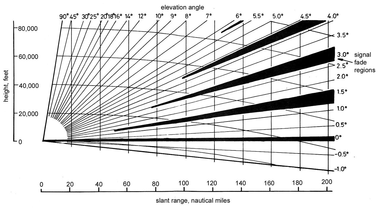
A pattern of fades for a radar
But if shorter wavelengths are better, why do the latest warships carry radars using wavelengths fairly close to those carried by Iowa in 1945? There are several reasons for this. First and foremost, waves shorter than about 7.5 millimeters are heavily absorbed by water vapor, to the point that they are useless for long-range detection even on land, to say nothing of operations at sea. But other effects tend to limit naval use of the shortest wavelengths in certain applications. A calm sea is a good reflector of radio waves, which means that there are multiple paths that a radar signal can take to and from the target. Because these paths are different lengths, the waves can reinforce or cancel each other out, creating a complicated pattern of zones where the signal strength can either climb or drop, depending on the various paths the signals take. In general, this affects short-wavelength radars more than long-wavelength ones, although radars with longer wavelengths have trouble seeing close to the horizon. In the past few decades, longer wavelengths have also proven useful at detecting stealthy aircraft, which are usually optimized against the shorter wavelengths used on land.
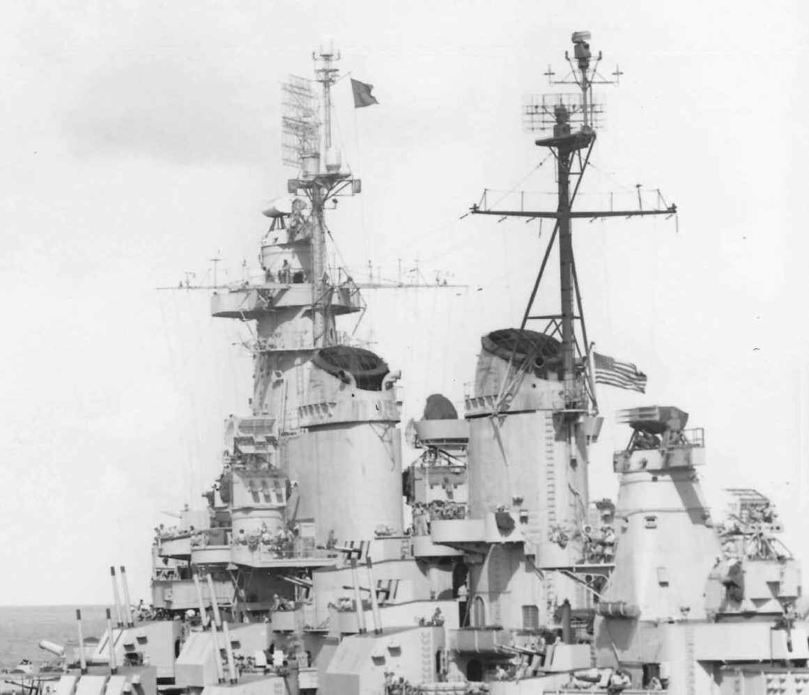
Iowa displays her radars, including air-search, surface-search and several kinds of fire-control
The result of all this is that a typical ship in the late 40s carried multiple different radars optimized for different purposes. The longest-range radar was likely to be an air-search radar operating with a wavelength of somewhere between 20 cm and 150 cm, intended to detect incoming aircraft a long ways off. This was known as a 2D radar, as its beam was narrow in bearing, but quite "tall", which means that it couldn't really tell the difference between a plane at low altitude and one at high altitude.4 This information is vital for directing fighters to intercept, and ships that needed said capability were equipped with a heightfinder, a specialized radar with an antenna that was tall instead of wide, producing a beam that was "short" and wide, with the altitude found by elevating the antenna until it could see the target. Complementing the air-search radar(s) was a surface-search set. This operated on much shorter wavelengths, rarely above 10 cm, and was designed to pick out targets on or near to the sea surface. Some surface-search radars were fitted with secondary antennas for "zenith search", as the elevation limit for the main air-search radar was rarely above 20°, and it was often possible for enemy aircraft to get into the blind spot above the ship.
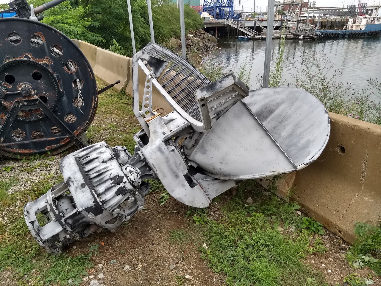
An antenna for a combined surface/zenith search radar
But all of these radars were primarily optimized for merely detecting targets, and none had the precision required to actually engage one. That was the job of fire-control radars, which operated at very short wavelengths and provided data directly to the fire-control system. But even a wavelength of only a few cm and a big antenna still resulted in a beam a few degrees across, which wasn't nearly precise enough for blind fire. Radar designers had to get clever to get the data they needed. The basic principle behind most of their solutions was the fact that a radar beam of a certain width isn't just a constant power within that width and then nothing. It's often described as a "lobe", and the power falls off smoothly from the centerline of the lobe to its edges, with the width of the lobe measured at the point when power drops to half of what it was at the center. Designers first made use of this through a technique known as "lobe switching". Two different antennas were built together, with their lobes very slightly offset from each other. The signal would be alternated between each side, and one would be sent to the A-scope with a slight delay, so that the two peaks were distinguishable. If the target was to one side or the other of the antenna centerline, then the peaks would be different, and the operator could simply rotate the antenna until they were even, giving sufficient accuracy for fire control. Later, this technique was bettered by a system known as "conical scan". In this, the main lobe is offset from the antenna centerline and spun. If the target is off-center, the signal will rise and fall as it spins, while a centered target will produce a constant signal. It's relatively easy to get a conical-scan radar to track a target, even with analog electronics, but it's also quite easy to jam, and modern radars use more sophisticated techniques.
Conical-scan radar
So what else does the radar design have to consider beyond frequency, antenna size and shape and scan type? There are two more major factors, pulse length and Pulse Repetition Frequency (PRF), both of which play into the average power that the radar can put out. Pulse length is exactly what you'd expect from the name, and a longer pulse length means more power, but it also makes it harder for the radar to distinguish objects that are almost the same distance away. If the start of a return from one object5 overlaps the end of the return from another, then they will show up as a single blip.6 But if you don't want that, the other way to increase power, and thus the chance of detecting a target, is to raise the PRF and send pulses out more often. The downside to a higher PRF is that it puts a limit on the maximum unambiguous range of the radar. The radar has no way of knowing which pulse a return belongs to, and thus has to assume that it's from the latest one. If a return in fact came from an earlier pulse, it will show up in the wrong place, creating a ghost target that can confuse operators. As a result, the PRF is usually set so that there's little chance of this happening.
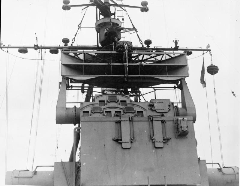
A British Type 274 Radar
Obviously, this is only an overview of basic radar theory, and there are whole books describing the details on each and every one of the topics I've skimmed over here. In later installments, I intend to cover the more advanced methods used in modern radar, as well as providing more details on the subjects discussed here.
1 For those who are not familiar with radar technology, I am going to try to lay out the basics with a minimum of math, focusing on understanding the principles involved. For those who are familiar with modern radar, I'm going to ignore a bunch of stuff to accomplish that goal, including just about everything after 1950. ⇑
2 The British, whose radar programs began with a focus on radar from land-based sites, used separate antennas for transmission and reception. It was easier to implement, and the imminence of war meant that it was also common for naval radars through 1942-1943, despite the difficulties of fitting two antennas. The American radar program began with the Naval Research Laboratory, and used single antennas from the start. ⇑
3 Frequency is how many times the radar's signal cycles in a second, while wavelength is how long each wave is. Because the speed of light is constant, wavelength is equal to 3*108/frequency. So a higher frequency means a lower wavelength, and vice versa. I will try to use wavelength here. ⇑
4 The interference "fades" can be useful in figuring out altitude for a 2D radar if no other means are available. ⇑
5 Remember that light travels 300m each microsecond, so a .5-microsecond pulse will be 150m long, and any object it reflects from will look at least 150m long even if it's a flat plate. ⇑
6 A longer pulse will also increase minimum range, as the radar has to switch over from transmit to receive, although during WWII this was dominated by switching time and not pulse length, which could be a problem for night fighters at close range. ⇑
Comments
How much did multiple RADAR equipped ships in the same formation step on each others toes?
Radars almost always had some ability to tune to other bands to reduce that problem, although it could be an issue. I don't have precise numbers to put on the problem, though.
As someone who uses radar for a living, good luck minimizing the math.
Getting all the constantly changing antennas mounted on the ship and working together right must have been an art. Possibly a dark one involving cutting vacuum tubes out of mechanical goats.
Ships generally only carried one of each search radar, but each mk38 director had its own mk13 radar set, right? Could they be used at the same time, do you think?
@echo
They could use both Mk 13s at the same time, AFAIK. Radars would have multiple frequencies they could use to avoid that kind of intereference. There are other kinds of interference which are still problems even on different frequencies, and brass models were (and maybe still are) used to figure them out. I have a picture of one somewhere.
Well, I am excited.
Naval RADAR pt2: Interference that makes sense.
Naval RADAR pt3: Interference that makes some sense.
Naval RADAR pt4: Interference that doesn't make any sense.
Naval RADAR pt5: UFOs: The fact that they make no sense is the best evidence that they are related to radar interference.
I always wondered about South Dakota at Guadalcanal, after all her radars but the one on secondary fire con was knocked out (impressive what cruiser guns can do to a battleship superstructure).
It seemed like the ship was totally blind at that point, I guess because plotting wasn't capable of receiving info from fire control? So the guys in secondary FC could pick out ships in the relatively narrow field of their radar, but had nobody to tell them who was what and which blip needed shooting?
Pretty much. FC radar doesn't have a wide field of view, and plotting takes a lot of practice and coordination. If they hadn't trained to get data from the director then trying to improvise that in combat isn't going to work.