
Last time I took a look at radar, I touched on some of the special techniques used to sort targets from background clutter, like moving target indication. But these are only a subset of a wide array of processing methods that have been developed to improve the efficacy of military radars, and which are well worth delving into at greater length.
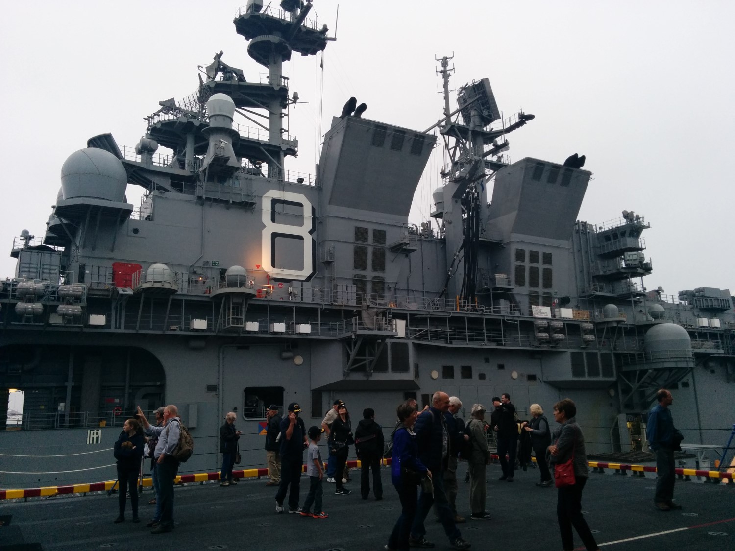
Radars on the island of amphibious assault ship Makin Island
The basic problem of radar is taking the raw electromagnetic signals picked up by the antenna and turning them into data that the crew can use to make decisions. From the first, engineers made improvements in this field, with PPIs being much easier to interpret than the A-scopes they largely replaced. Nor was this process confined entirely to the electronics themselves, as CICs and plotting allowed dots on a screen to be turned into tracks for the Captain or Admiral. Postwar, efforts to extract more information and automate its collection continued, producing a series of innovations which are standard on military radars today.
One of the fundamental problems with WWII-era radars was that they gave designers a stark choice: either the radar could be dedicated to tracking a specific target, as was common for fire-control radars, or it could search broadly, reporting everything it found. This was a particular problem for aircraft, which unlike ships generally couldn't afford to have multiple radar sets or a suite of dedicated operators for turning the output of a search radar into tracks. The obvious solution was to replace the operators with electronics, thus giving a scanning radar tracking capability, generally known as Track-While-Scan (TWS). At its most fundamental, TWS involves placing a "gate" around the expected position of the thing being tracked, and looking for something in that gate every time the radar examines that portion of the sky. For the next scan, the gate is then centered on where the target was last time, and the process repeats. More advanced systems will extrapolate the likely position of the target based on its past movement, and even automatically enlarge the gate in an attempt to reacquire the target if it maneuvers out of the original gate. Early systems could only track one or maybe a handful of targets, but as computers developed, more and more tracks could be added.
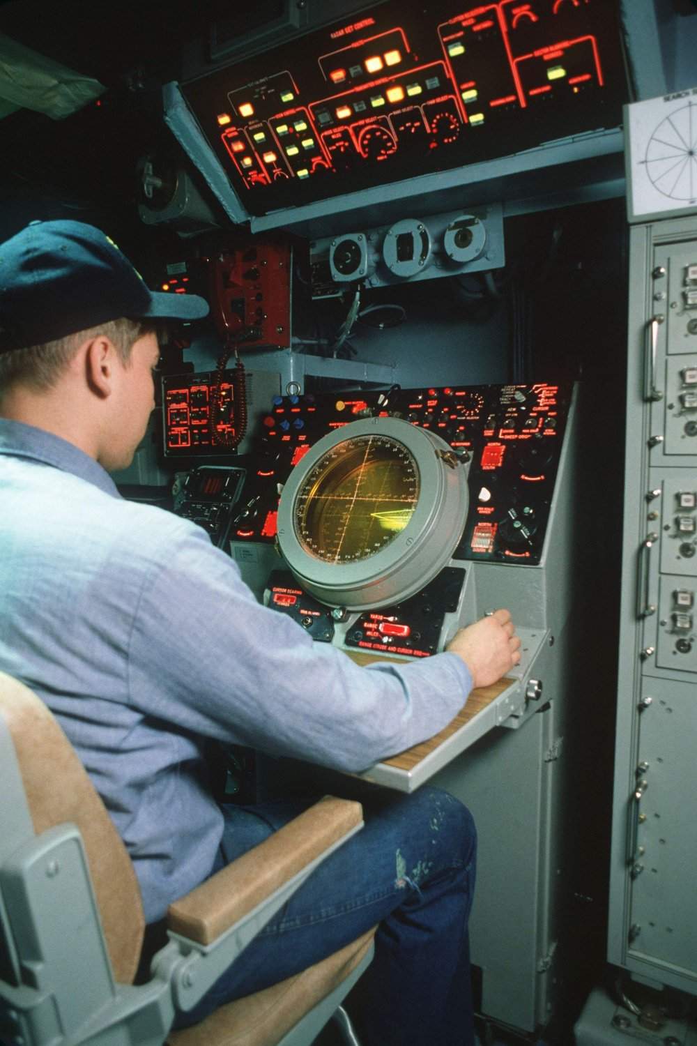
An operator at the console for Iowa's SPS-49, a radar with TWS and ADT
TWS is particularly powerful when combined with another technology, automatic target detection (ATD). While experienced human operators are quite good at picking blips out of noise, they can't be completely vigilant at all times. Electronics can, and from the 60s onward, many radars were set up to automatically maintain a "Constant False Alarm Rate", looking for any signal that reached a certain threshold above the prevailing noise. This is also useful when faced with jamming, as the ATD system will just raise the signal strength required to pick up a target and keep operating, instead of being washed out. When ATD and TWS are used together, they can come close to replacing human operators, greatly improving performance in the face of saturation attacks. Today, computers allow even better target discrimination, as returns which cross the detection threshold can still be ignored if they don't meet other criteria. For instance, many modern air-defense radars are set up to ignore targets below a certain velocity, although this can backfire, as during an early Aegis deployment when a contact picked up by other radars and ignored as spurious turned out to be a sightseeing Cessna.
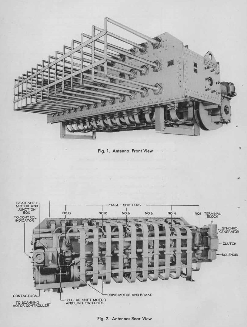
Mk 8 gunnery radar
But systems like TWS are only as good as the information they get from the radar signal, and designers have also done extensive work to collect as much data as possible as quickly as possible by shaping how the radar signal is transmitted and received. One example of this is monopulse radar, a technique used to compare portions of a pulse to each other and get a much more precise track than is possible from a simple lobe, or even techniques like conical scanning. A typical monopulse radar might have four feed horns,1 positioned so that their beams are spread out very slightly. The returned pulse is picked up at different strengths in each horn, which can then be used to give a much more precise indication of target location.2 Because monopulse radars do their comparison with a single pulse instead of a sequence of pulses, they are far less likely to be confused by things like fluctuations in the target's RCS, to say nothing of their improved resistance to jamming.
How a phased array works
But monopulse radars are far from the only clever use of beams in modern radar. The gold standard here is a type that has revolutionized military radar since the 1980s, phased arrays. A phased array is made up of a grid of small elements, each of which has a simple fixed antenna. By varying the phase3 of the signal sent by each element, a beam is created where the fronts of the spherical signal from each element line up, and the process is reversed when receiving. The biggest advantage of this is that can be steered instantly throughout essentially the entire hemisphere facing the radar, which allows far greater flexibility than from any previous radar system. While phased arrays are generally seen as a modern phenomenon, they first went to sea during WWII, with the Mk 8 used by the USN for main battery fire control during WWII, including aboard the Iowa. It used an array of simple transmitters and a mechanical scanning system to steer the beam in train, giving a bearing accuracy of .1° out of a 2° beam. This also allowed it to both track a target and see nearby shell splashes, a major advantage in surface gunnery. However, it was high-maintenance, and the subsequent Mk 13 reverted to a more straightforward mechanically-scanned parabolic antenna.
SPY-1 array aboard Wayne E Meyer
Proper phased arrays first went to sea in the early 60s, in the form of the SPS-32/SPS-33 combo carried aboard Enterprise and Long Beach. This was an ambitious system, and it didn't work all that well, so phased arrays had to wait another two decades before seeing wide use in the form of the SPY-1 carried by the Ticonderoga class cruisers. This was truly revolutionary, as it could not only search all around the ship much faster than existing radars, a great help against the threat of saturation missile attack, but also was capable of generating much more precise tracks for Aegis, the heart of the new system. This in turn meant that conventional guidance radars were no longer needed, as the missiles could be steered via a programmable autopilot until just before impact, further increasing capability against saturation attacks. Today, phased arrays are at the heart of all naval air-defense systems, although implementation varies. Some systems use multiple arrays to look in all directions at once, such as the SPY-1, while others, most notably the British SAMPSON, are mounted higher in the ship to push out the radar horizon and spin to provide full coverage. SAMPSON uses only two faces, but spins quite quickly to give full coverage.
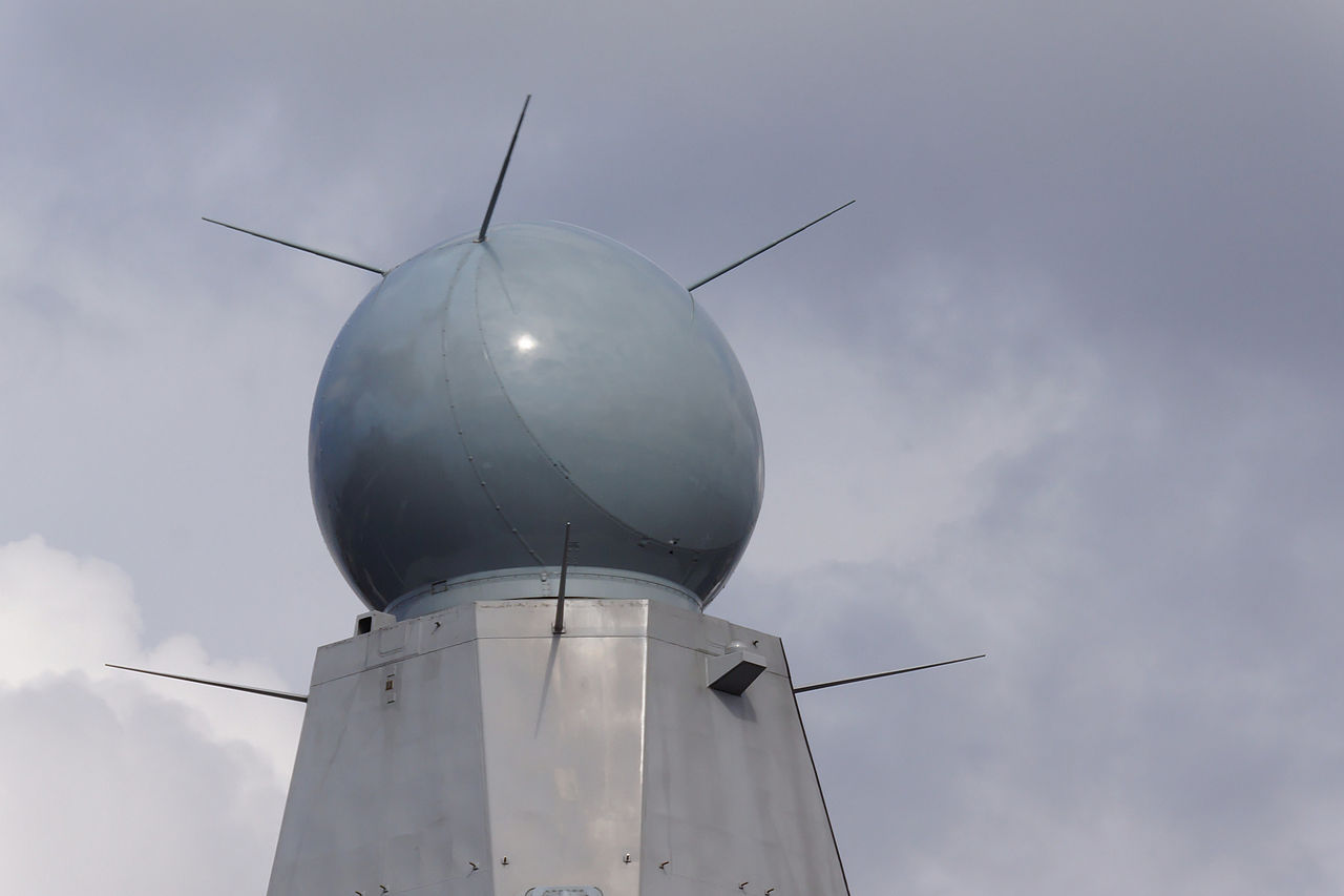
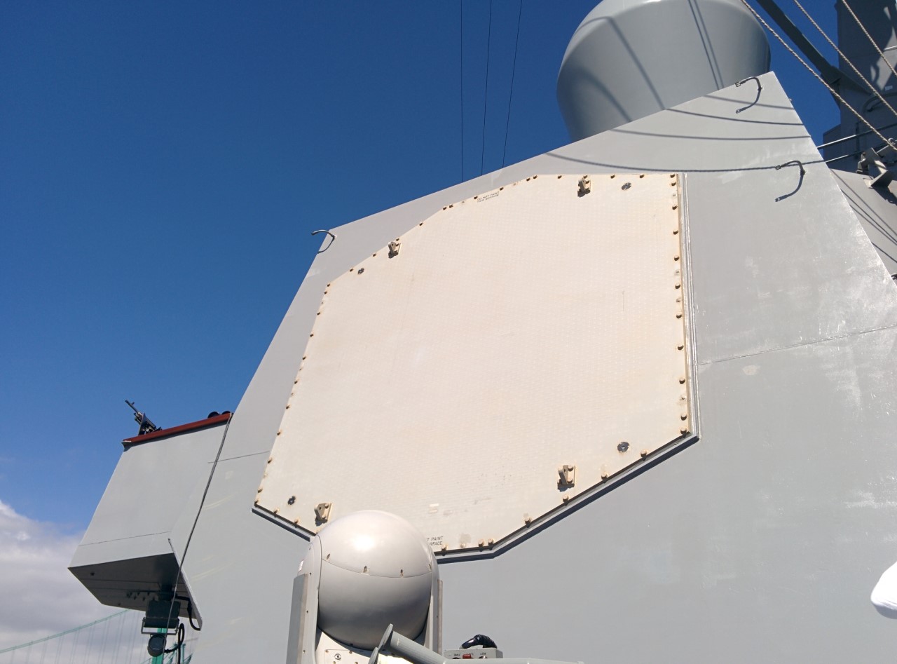
SAMPSON AESA, with the disconnect between sloped array and cover faintly visible
Today, the latest major advance is Active Electronically Scanned Arrays (AESA). Older phased arrays like SPY-1 use a single signal source, with the resulting signal passing through an array of separate phase-shifters to form the beam. AESAs instead use individual transmitter/receiver elements, which allow things like the creation of multiple separate beams at different frequencies and for different tasks, allowing even more rapid search and adding capabilities like electronic warfare and communications to the arsenal of what was previously only a radar. The flexibility of AESA radars also makes them much harder for ESM systems to detect, or to identify once detected. AESAs do have some disadvantaes, as each transmitter/receiver is heavier than a phase shifter and requires more cooling. Most AESAs, such as the Dutch APAR, operate at short wavelengths, which mean that they are backed up by longer-wavelength air-search radar, usually a PESA. The short wavelength can be an advantage, as APAR can provide illumination for SM-2 and ESSM SAMs, a capability the S-band SPY-1 lacks. Recent developments have seen the frequency fall into that region, as used on the SPY-6 planned for the Flight III Burkes.
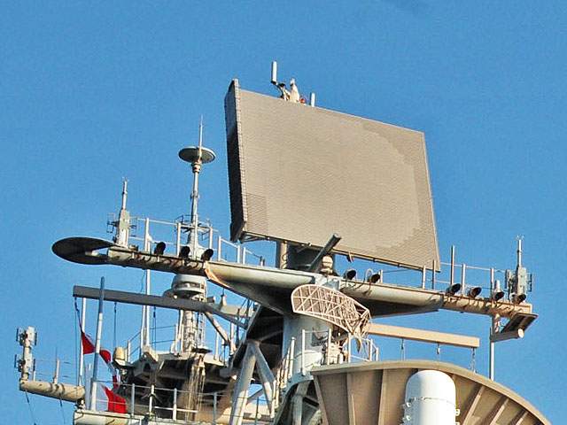
SPS-48 FRESCAN radar, with waveguide on the left side
But while phased arrays are the future, naval radars tend to be surprisingly long-lived, and as a result, many earlier rotating systems also remain in use. Most of these use fairly standard antennas, but some are based on a clever quasi-phased-array system known as Frequency Scanning or FRESCAN. These rotate like normal radars, but use signals of different frequencies to scan in elevation. Essentially, the transmitted signal is passed through a complicated waveguide to a flat-plate array, made up of slots out of which the signal escapes. The waveguide places a certain length of delay between each slot, which in turn allows it to serve as a simple phased array, focusing the signal in a specific direction. This technique is actually remarkably old, and was used by a number of very early radars to produce their beams, although the beam always emerged in a fixed orientation relative to the antenna. What makes FRESCAN work is that signals of different wavelengths will emerge from the fixed-length waveguide at different phases relative to each other, and careful selection of these produces beams at different elevation angles.4 FRESCAN radars do have some drawbacks. They have to use relatively long pulses to keep the width of their beam down, which in turn limits range resolution, and they can't vary their frequency like more conventional radars. Despite this, they remain reasonably common today, such as the SPS-48 used on most American carriers and big-deck amphibious ships.
1 The technical term for the thing which outputs the signals that then bounce off the main antenna. ⇑
2 As best I can tell, some monopulse radars send out a single pulse and have multiple receive horns, while others send out multiple beams. All count as monopulse because they do comparisons on a single pulse instead of multiple pulses. ⇑
3 Phase is where in the cycle a wave is, usually relative to another wave. So two signals where one was at the highest point while the other was crossing zero would be 90° out of phase. ⇑
4 To clarify this with a bit of math, say that there's a waveguide of length X between each slot. If a signal of wavelength X is sent in, each slot will be in phase and the beam will be straight out. If the signal is wavelength 1.1X, each will be 36° out of phase, and the beam will be offset. ⇑
Recent Comments