
I've previously looked at the basics of naval radar, but there is still a lot of ground to cover. This time, our main subject will be noise. In a typical, simplified model, the radar reflects off of its target and comes back, showing up as a clean blip. In practice, it's far from that simple. Every radar return off of a target comes back mixed with other signals - reflections from the sea or other nearby objects, random electrical noise, echoes from previous pulses, signals from other radars and even intentional interference in the form of jamming. The radar designer's task is to figure out how to boost the signal and suppress the noise, and then distinguish between the signals they want and the ones they don't, and they have come up with a variety of tricks to do so.1
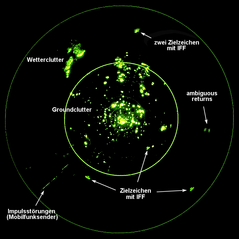
A scope with various forms of interference on it
But before we get to noise, it's worth taking a digression to talk about how the radio spectrum is divided up, usually into a set of "bands". There are several different systems, the two most common both using letters to designate the bands. One is normally used for most radar, while the other is the standard for electronic warfare. The latter system uses letters A-M, from long to short wavelength, while the former uses an array of letters including C, K and L, which can cause confusion. We'll primarily use the radar system, which is in wider use, and which can be found in the table below:
| Band | Frequency (MHz) | Wavelength (cm) |
|---|---|---|
| VHF | 100-300 | 300-100 |
| UHF | 300-1000 | 100-30 |
| L | 1000-2000 | 30-15 |
| S | 2000-4000 | 15-7.5 |
| C | 4000-8000 | 7.5-3.75 |
| X | 8000-12000 | 3.75-2.5 |
| Ku | 12000-18000 | 2.5-1.67 |
| K2 | 18000-27000 | 1.67-1.11 |
| Ka | 27000-40000 | 1.11-0.75 |
The band structure is useful because each band tends to have distinct characteristics and uses. For instance, rain is essentially invisible to radars with wavelengths above 10 cm,3 and things get worse as the wavelength approaches the dimensions of the raindrops themselves, in the K band. Even X band is reflected strongly enough that weather radars tend to be in that band, but this obviously limits utility for military applications, and air-search radars tend to operate in S and C bands as a result. Returning to our original subject, noise tends to decrease with wavelength between the L and X bands before increasing again in the K band.
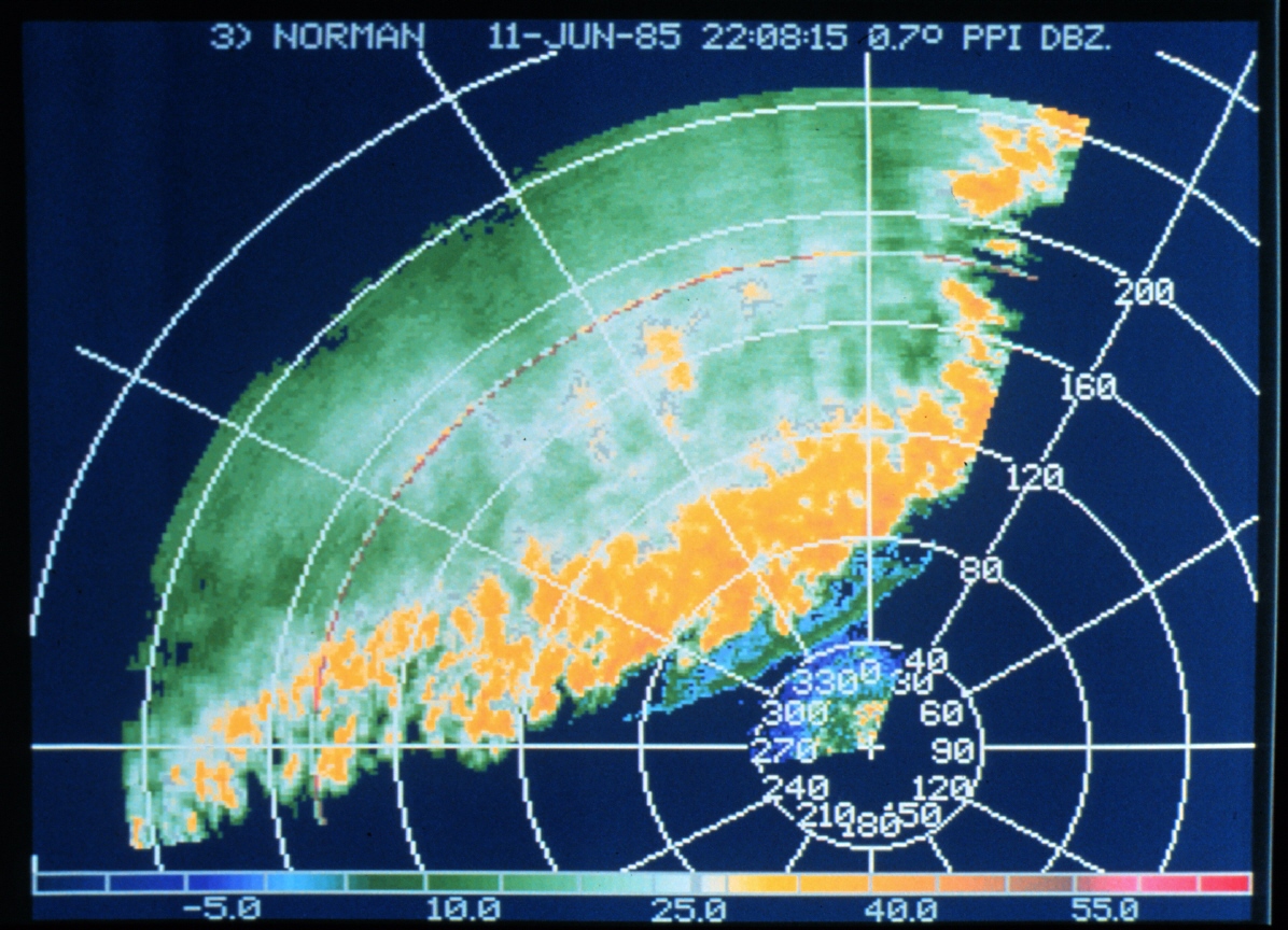
A weather radar display, probably using the X band
The simplest way of dealing with most natural noise is integration, building up signals over multiple echoes. The simplest way to do this is to add together multiple pulses, as noise tends to fluctuate very quickly, while signals are consistent between pulses. This can be done fairly simply with analog circuits, but also tends to require a high PRF to be effective, in turn limiting unambiguous range. More sophisticated methods involve using complicated pulses, which can be pulled out by signal processing. A simple version of this is pulse compression, which sends a pulse that is "chirped", with frequency increasing or decreasing throughout the pulse. The returning pulse is then processed, delaying each different frequency so that they are "stacked", as if they were sent out at the same time. In addition to significantly improving the range resolution of the radar,4 this also improves the signal-to-noise ratio in the face of both natural noise and jamming. Chirping was common with early pulse-compression radars because it could be performed by analog electronics. Digital systems produced since the 80s use other techniques, most notably analyzing the phase5 of the pulse.
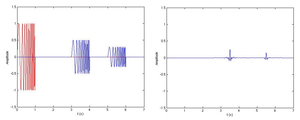
A demonstration of pulse compression. Original signal to the left, compressed signal to the right.
But all of these techniques, though effective against noise, are far less so against clutter. Birds don't cancel each other out, or move 500' between one scan and the next. Other methods are required to pick real targets out of the flood of real signals that aren't of interest to the radar's operator. For air-search radars, this is relatively simple, as nothing natural moves nearly as fast as an airplane. The simplest way to do this filtering is to look at the Doppler shift in the frequency of the returned signals,6 discarding anything which shows no motion, or at least no motion relative to what is expected for a non-moving object. While this is simple to implement and works reasonably well in most cases, it does have the drawback that a plane flying perpendicular to the line of sight to the radar will be interpreted as non-moving and disappear off the screen. More sophisticated Moving Target Indication (MTI) systems use some form of memory to compare one pulse to the next. The most basic MTI technique is to simply remember the previous pulse, then invert it and mix it with the new return. Anything which is in the same place as before will be cancelled out, while moving targets will still show up. More modern systems use phase information. A non-moving target will always have a return with the same phase on each subsequent pulse, while a moving target will be at a different distance from the radar and thus probably return a different phase.7
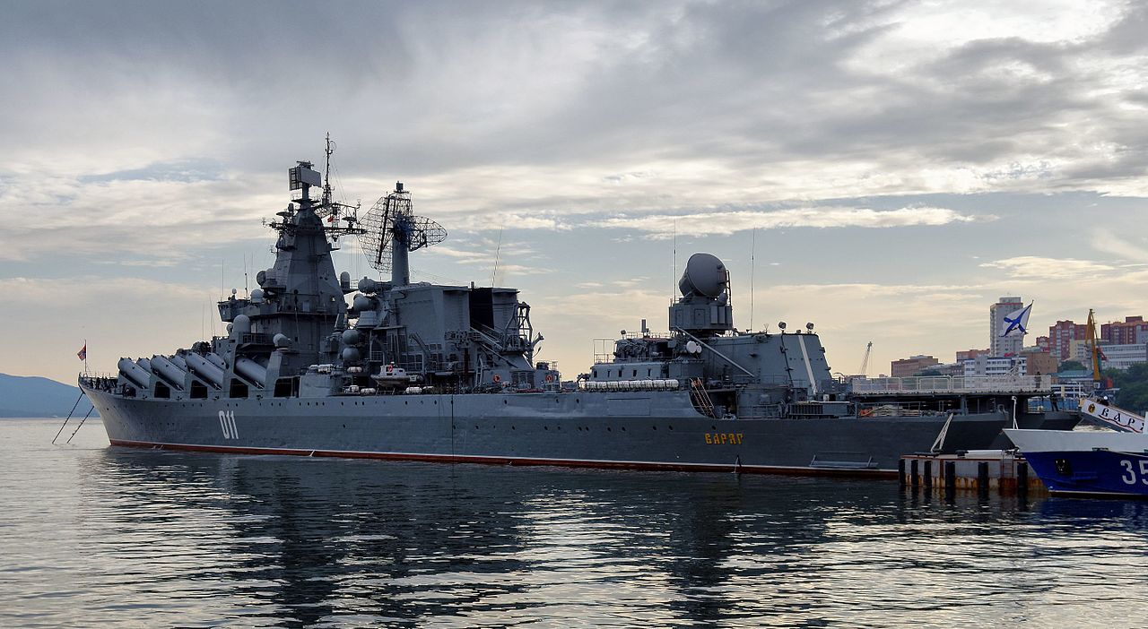
Russian cruiser Varyag shows the cluster of antennas typical of earlier warships
Another source of noise worth looking at is other radars. Particularly in the early days, a radar would display all signals of the appropriate frequency, which meant that another radar operating at the same frequency would show up as a false set of returns. As a result, radars are designed so that they can be retuned within their band so that multiple radars of the same type can be operated in the same group. The number of slots is limited because radar signals don't come out as a single frequency, and for complicated mathematical reasons, the bandwidth each signal takes up is inversely proportional to the length of the pulse. This is much more of a problem for low-frequency/long-wavelenght radars than for higher-frequency ones, as each slot takes up more of the available space in the band. Retuning is also a vital ECCM feature, as it gives the opportunity to find a clear frequency in the midst of jamming.
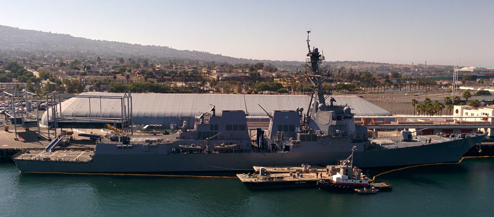
The cleaner lines of a modern warship, the Wayne E Meyer
Another form of interference comes from the structure of the ship itself. Warships have long been the densest concentrations of radar and radio equipment on the planet, which makes finding places to mount it all quite difficult. Ideally, each radar would be mounted high in the ship, to extend its range, and with a search field unobstructed by any other equipment. Some ships approach this ideal with their most important radar, most notably the SAMPSON on the British Type 45 destroyer, mounted inside the ball at the top of the mast, but the vast majority of radars are fitted in locations where they will radiate into other antennas and structures, producing complex patterns. To ensure that there aren't any large blind spots or other disastrous problems, antenna arrangements are worked out on scale models made of brass, wired up to transmit the relevant signals, which are then measured. Even today, this remains the best and surest way to deal with the complex tangle of electronics that is the modern warship, although this has become less necessary over the last 40 years or so as modern electronics allow multiple antennas to be combined, such as the four faces of the SPY-1 radar used for Aegis, and the ability of modern radars to serve multiple functions cuts down on the total number required.
We'll take a look at other aspects of naval radar next time.
1 There's going to be some overlap between this post and my post on ECCM, because a lot of the same techniques used on natural noise also work on jamming. ⇑
2 The K-band is subdivided because the 1.67-1.11 cm range sees heavy absorption from water vapor in the atmosphere, giving Ka (K above) and Ku (K under) that operate on either side of the absorption zone. ⇑
3 Obviously, raindrops are smaller than this, but 10 cm is the distance over which raindrops fall in a coordinated manner. ⇑
4 This is useful in countering clutter by breaking up the return into small "cells", and increasing the chance that the cell with the actual target will show a strong echo relative to the cluttered cells. ⇑
5 Radar signals are waves, and phase is essentially where the peaks and troughs of that wave are located. ⇑
6 Essentially, frequencies change between moving things, because the waves arrive closer together or further apart. The classic example is the sound of a train passing by, which goes from high to low as it moves past. ⇑
7 This kind of MTI has "blind speeds", where the target just happens to move the right distance to shift the phase 360° or a multiple thereof. This can be dealt with by using a different PRF, which will shift the blind speed, and also confuse jamming. I am also not sure how they deal with it if the radar itself is moving, which it would be for almost all cases at sea. I assume they handle this these days by throwing it all at a computer, but details of that kind of stuff are very sparse. ⇑
Comments
Typos: "essential invisible", "fairsly", "the invert", broken image tag of Varyag, "wavelenght".
"flying parallel to the line of sight" is probably supposed to be perpendicular.
Why are the models for radar testing made of brass? Does brass have just the right conductivity or are there other reasons?
I’d guess it’s more to do with workability than anything else. Brass is presumably the right balance of easy to work in and tough enough to not have to be super-careful with. Note that these are not small models. The one I've seen most closely was the 1:48 scale model of USS St. Paul onboard Massachusetts. (I'd misremembered it as being on Salem, which is why I only found the pictures just now.)
Low resistivity and no ferromagnetism probably help too. (compared to ferrous metals)
If it's a 1:48 model, do they need to run all the scale radars at 48 times the frequency of the real ones?
@Lambert,
I imagine they would have to scale the wavelengths along with the ship they are modelling. And hope that their models are faithful in all the details that actually matter.
I recall a claim (never proven) that one particular aircooled engine had some interesting effects because the fin spacing on the engine created weird reflections for a particular radar frequency.
MTI blindspeeds: they depend on the PRF. Thus the development (even in radars built wholly from analog components) of the ability to either continuously tune the PRF or to switch between a few preset ones; then the ability to use a short programmed pattern of pulse repetition; then with digitally-controlled radars, using a random number generator to set the delay between pulses (as a precursor to more complete LPI modes developed even later, but already giving a headache to anyone who tried to jam the radar in a smart way).
That makes a lot of sense. Any idea how they handle the radar itself moving?