
While battleship designers had long tried to protect against underwater attack, the first months of World War One showed the full extent of the threat posed by torpedoes and mines. The existing underwater protection systems installed in pre-dreadnoughts proved totally inadequate, and numerous vessels were lost to these causes. Even the dreadnoughts were not immune, as shown most notably by the loss of Audacious in the first months of the war.
Bulge on monitor HMS Glatton
The British quickly began to look for ways to improve protection, finding one in the form of the bulge. In their simplest form, these were just expansion chambers mounted on the outside of an existing hull, with a free-flooding liquid layer behind the air chamber. This increased the depth of the TDS, and provided an effective air-liquid layer system. Bulges were first used on ships operating close inshore, a particularly good area for submarines and small torpedo craft, and proved very successful. Even the earliest bulged ships took torpedo hits with no damage. The only drawback was a slight reduction in speed,1 and even battleships were soon being fitted with bulges. Ramillies and later capital ships were fitted with them while under construction, while older ships gained them in refits.
A torpedo bulge, showing outer air chamber (red) and inner free-flooding section (blue)2
The British launched an extensive series of model tests during the war, and quickly discovered that small, sealed tubes would be an effective energy absorber, replacing the liquid layer. They would crush under the explosion, absorbing energy and fragments, and the 9" tubes used in Hood allowed her bulges to be half the width of those in a conventional ship. Unfortunately, because the tubes filled the space, it was impossible to paint them or do other maintenance, and they corroded badly. As a result, the British adopted a liquid layer system on the Nelsons and later battleships.3
As if the TDS designer's task was not hard enough, people were inventing new ways to attack ships underwater as early as 1911. The first effort was the Davis Gun, an 8" recoilless weapon intended to fire an HE shell through the side of the ship. This would totally defeat existing systems, and both the USN and RN looked at fitting underwater armor. They soon determined that this would compromise the effectiveness of the TDS against torpedoes, due to the fragments produced by the inflexible armor, and that the Davis Gun was not particularly effective.
Cross-section of the Nelson class
The threat reappeared during the interwar era in a slightly different form. Designers had assumed that any shell which hit the water would be either deflected upward or quickly stopped before it got deep below the waterline. Until the great increase in combat ranges during WWI, this had been a perfectly valid assumption, but the steeply-falling shells of long-range battle could penetrate deep below the surface of the water before losing speed or going off. This raised the specter of shells falling short of the ship and penetrating through the unarmored TDS deep into the bowels of the target. Only the Japanese made a sustained attempt to exploit this mechanism, but designers the world over had to take steps to protect against it.
Armor and TDS of Iowa at Frame 101
The first generation of treaty designs were largely too tight to do much about this. The North Carolina class were fitted with armored patches over their magazines, but the follow-on South Dakota and Iowa classes had their angled armored belts extended down to the bottom of the ship, forming the third bulkhead of the TDS. This also meant that the armored deck and belt didn't threaten to trap the gas jet inside the vessel, a serious problem on the King George V class. The urgency of the situation meant that the American ships were laid down before the systems could be tested in full scale, and the tests were a rude surprise, with the rigidity of the armor proving a dangerous weakness. The initial plan for the 4-void system had been a traditional void-liquid-liquid-void, but it was changed to liquid-liquid-void-void when tests showed that that arrangement would be more effective. Further tests showed that there were structural weaknesses in the system for the Iowas, and BB-65 and BB-66 would have had a modified system, estimated to be 20% more effective, had they been completed.
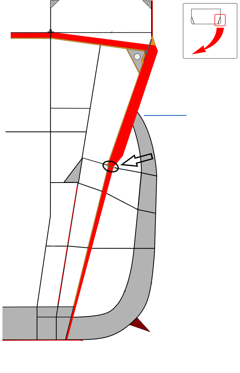
Cross-section of the Yamato class, with joint circled
The Japanese went even further, giving equal weight to underwater shell hits and torpedoes. For reasons that are not entirely clear, they ignored the use of liquid layers entirely, apparently believing that the thick lower belt was adequate compensation. This was not the case, and to make matters worse, the joint between the upper and lower belts was designed improperly, with incorrect scaling from the model tests. It relied entirely on the shear strength of rivets, which failed under relatively light torpedo hits on Yamato, Musashi and Shinano, ultimately leading to the loss of all three ships.
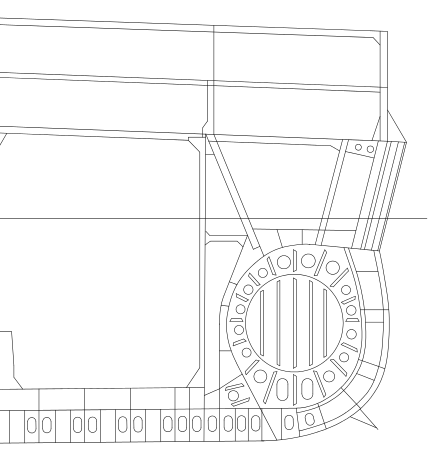
The Pugliese system of the Vittorio Veneto class
An innovative attempt to reduce the size and weight of TDSs was the Italian Pugliese system. The lower corner of the hull was filled with liquid, either water or oil, and an air-filled cylinder was placed in the center of it. In theory, the cylinder would collapse under explosive loading, the sudden increase in available volume robbing the gas jet of its energy. The holding bulkhead surrounding the liquid had to be strong enough to withstand the pressure until the cylinder collapsed, which was the problem with the system as implemented on the Italian Littorio class. The riveted joint at the bottom of the bulkhead was not strong enough, and tended to fail before the cylinder collapsed, causing extensive flooding. It was also very difficult to build and repair, due to the complex curves involved.
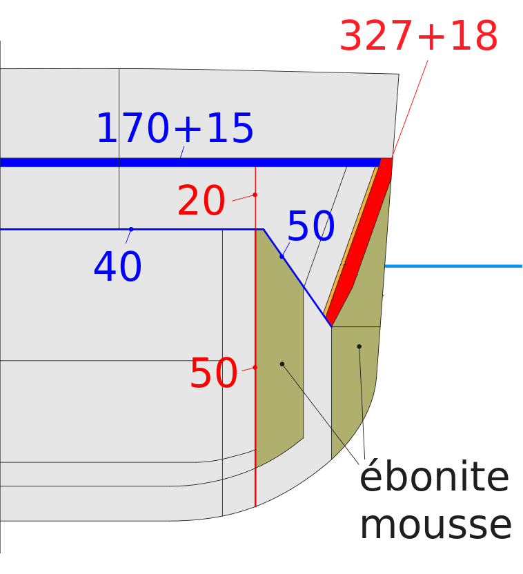
A section of the Richelieu class TDS
The last of the treaty battleships, the French Richelieu class, had a very effective TDS of their own, deep and of largely conventional design, with an interesting twist. A material called Ebonite Mousse was installed in some of the void spaces. This was the last in a long line of attempts to use something that would prevent flooding into void spaces when the system was damaged. Most early attempts had failed, notably the use of wood pulp, which rotted. However, the Ebonite Mousse, a gum rubber foam, was a success, requiring little maintenance and proving effective in tests.
All of these systems suffered from insufficient depth near the ends. In fast battleships, which all of the treaty ships apart from the Nelsons were, the need for fine ends to achieve speed conflicted with the need for deep TDS. Even the best TDS was of no use against torpedoes that did not hit it, and it proved totally impossible to protect the shafts and rudder. A hit in this location ultimately doomed Bismarck, and constituted a serious vulnerability in all ships.
Another threat that a TDS could not counter was the threat of an attack from underneath. For many years, this was not a serious problem, but it became a concern during the runup to World War II. I'll talk about it in more detail later.
1 There were a few cases in which ships didn't lose speed, due to some oddity of hydrodynamics, but they were the exception, not the rule. ⇑
2 The circles in the free-flooding section are lightening holes (which make things lighter) in the bulkheads used to give rigidity to the bulge. ⇑
3 The Nelsons used only water in their liquid layers. Some of this was to avoid the maintenance problems of mixing oil and water in a given tank, but the water in the TDS was not claimed as part of the ship's weight under the Washington Naval Treaty, essentially making it free to the designers. ⇑
Comments
A lot of diagrams and plans I've seen seem to assume that "waterline" is a constant level along the side of the ship. Yet in high seas, or during high-speed turning maneuvers, wouldn't there be a substantial difference in what was and wasn't exposed to air? How did naval designers allow for that effect?
Usually, that was dealt with by making sure that the belt went below the waterline. I'm not sure what torpedoes did in rough seas, but they're heavy enough to not be able to run up and down easily. They probably track fairly close to their average depth. I do know that on a few ships (I believe it was the North Carolina) some of the armor was tailored for the waterline as the ship was moving instead of assuming a stationary ship. But it's been a while since I looked into that.
Thread necro comment, but ...
Drachinifel in his recent video on the loss of the Hood hypothesises that the fatal hit struck below the belt in the trough of the bow wave.
The best writeup on Hood's loss I've seen is at NavWeaps, and hypothesizes something similar, although the details may be different. Doing a version myself is on my to-do list, but it's going to be a while.
Good morning.
There is a little mistake. The Vittorio Veneto class used the Pugliese system (not Puligese), from the name of the engineer Umberto Pugliese.
Ah. My bad. Should be fixed now.
The part about the Pugliese system is based on outdated information (mainly the Garzke & Dulin comments).
The recent book by Bagnasco and De Toro basically myth-busts the "riveted joint" thing (there was no riveted part in the system, only welding), and points out that there is no proof that the Pugliese SPS was any more difficult or longer to repair than standard layered systems. And other criticism of the system is debunked as well.
I have both of their books on Italian battleships, and I don't see any confirmation that the critical joint was riveted vs welded. There was welded material in the TDS, but there was also riveting (Littorio class, p.57, right column halfway down the page), and given the general difficulty of welding armor steel, my guess is that the outer bulkhead was riveted. I also don't see any comments on the difficulty of repair on any of the pages listed in the index on the Littorio class, and even if there isn't any proof by someone doing a side-by-side study, it's pretty obvious that it's going to be harder to build and repair than a system with relies primarily on flat bulkheads, just because of the nature of manufacturing processes.
Reading the article about Cruiser killers: https://www.navalgazing.net/Cruiser-Killers I'm not sure what sort of ships had a substantial TDS. Was it just Battleships, Battlecruisers and the better protected Carriers? Torpedoes seem like a sufficiently serious threat, primarily from aircraft, but also from surface vessels and submarines, that a TDS might be more valuable than protection from shells above 6"
The big problem is just that any sort of effective TDS is going to take a lot of volume, which means a significantly bigger ship. And if it's not going to be effective, you're better off just relying on compartmentalization and redundancy. So it was unique to carriers and battleships/battlecruisers, or at least I can't think of any exceptions offhand.
And while ships smaller than Alaskas were built with TDSs between the wars, presumably this was possible because they were slower, and had to defend against torpedoes with smaller warheads?
They looked at fitting the Alaskas with a TDS, but it would have driven up size too much. The Alaskas are on the smaller end of the cruiser-killer type, and unusual in not having one. But some of that was also American range requirements, which were much longer than anyone else's.
I take it they didn't consider an oil filled TDS? Or were those still a net reduction in range? It seems like it should be possible to add a system that protects from torpedoes and extends range, at some cost to speed.
The US used oil in all of its TDSs. I'm sure they looked at that, and at a guess the void spaces they'd have needed drove up size too much even with the oil tankage.
@Alexander: in theory yes, slower ships can afford thicker side protection (both TDS and belt armor) than faster ships of the same weight.
The obvious option is to spend less weight and space on engines and more on protection.
Another possibility is to be shorter/shallower and wider (= more drag but less side area to protect). This also has other potential advantages for monitors and old battleships (though I don't know whether these were significant in practice). Shallow draft lets them get closer to shore targets. Wider beam potentially reduces roll and hence improves gun accuracy, though by this time period fire control was plausibly good enough that this wasn't the main limiting factor.